R&D
- Jul 1, 2016
It Can Groove, But Does It Jive?
B.A. Liechty, Research and Development Engineer
R.C. Dillion, Engineering Technician
In August of 2015 progress towards making wire with microgrooves in the guidewire size range was summarized in A New Take on Wire Geometry – Functional Grooves. Now the focus has shifted to comparing the mechanical performance to that of solid round wire.
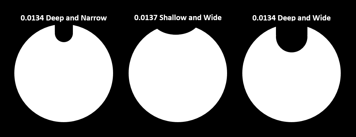
Five straightened 304V (ASTM A313) stainless steel wires were tested: three grooved (described by nominal OD and groove shape), and two round. Actual OD refers to each wire’s round diameter as measured on a bench micrometer, while the Equivalent OD refers to the round wire diameter that has an equivalent cross sectional area to that of each grooved wire.
Sample Identification
| Sample | Equivalent OD | Approx. Grooove Area |
| in. | % | |
| 0.0134 Deep and Narrow | 0.01304 | 6 |
| 0.0137 Shallow and Wide | 0.01334 | 6 |
| 0.0134 Deep and Wide | 0.01270 | 11 |
| 0.012 Round | N/A | N/A |
| 0.015 Round | N/A | N/A |
General Groove Proportions
Thus far, much of the grooved work has been focused on spring temper 304V. Tensile strengths higher than 325 ksi are achievable when the missing cross section due to the groove is accounted for.
Tensile Testing Results
| Computed using Actual OD | Computed using Equiv. OD | ||||||
| Sample | Elong. | Tensile Str. | Yield Str. | Modulus | Tensile Str. | Yield Str. | Modulus |
| % | ksi | ksi | Msi | ksi | ksi | Msi | |
| 0.0134 Deep and Narrow | 2.2 | 310 | 271 | 26.6 | 327 | 286 | 28.2 |
| 0.0137 Shallow and Wide | 2.6 | 323 | 243 | 26.2 | 344 | 259 | 27.9 |
| 0.0134 Deep and Wide | 2.7 | 293 | 224 | 24.1 | 328 | 251 | 27.0 |
| 0.012 SLT | 2.5 | 337 | 257 | 28.6 | |||
| 0.015 SLT | 2.6 | 299 | 229 | 27.7 | |||
Rotary beam fatigue testing was performed in order to see if the grooves significantly impact fatigue life. There was a large amount of overlap between the grooved and round wire results.
Fatigue Testing Results @ 0.75% Strain
.png)
Fully reversed (R = -1) rotary beam fatigue @ 60Hz
The grooves necessarily spiral around the OD of the wire, so torsion testing was performed to see if the handedness of the groove (left hand helix vs. right hand helix) significantly impacts torque characteristics.
Torsion Testing Results
| Sample | Groove Pitch |
Test Direction | Revolutions to Fracture |
Yield Strength |
Shear Strength |
Shear Modulus |
| in. | ksi | ksi | Msi | |||
| 0.0134 Deep and Narrow | 0.63 | Clockwise | 191 | 148 | 241 | 9.3 |
| Counter Clockwise | 210 | 121 | 240 | 8.8 | ||
| 0.0137 Shallow and Wide | 0.50 | Clockwise | 255 | 119 | 235 | 9.1 |
| Counter Clockwise | 217 | 124 | 227 | 9.0 | ||
| 0.0134 Deep and Wide | 0.47 | Clockwise | 249 | 120 | 240 | 7.9 |
| Counter Clockwise | 265 | 111 | 234 | 6.8 | ||
| 0.012 Round | N/A | Clockwise | 274 | 120 | 177 | 5.5 |
| Counter Clockwise | 327 | 133 | 208 | 6.2 | ||
| 0.015 Round | N/A | Clockwise | 200 | 155 | 235 | 9.7 |
| Counter Clockwise | 233 | 151 | 232 | 9.8 |
Differences in bending stiffness were anticipated, depending on how the groove was oriented relative to the point of contact with the pin the wire was being bent around.
Bend Moment Testing Results
| Sample | Orientation | AVG Yield Load | AVG Ultimate Load |
| N•cm | N•cm | ||
| 0.0134 Deep and Narrow | A | 1.01 | 1.41 |
| B | 1.05 | 1.47 | |
| C | 1.01 | 1.40 | |
| 0.0137 Shallow and Wide | A | 1.10 | 1.56 |
| B | 1.16 | 1.63 | |
| C | 1.07 | 1.53 | |
| 0.0134 Deep and Wide | A | 0.89 | 1.25 |
| B | 0.98 | 1.41 | |
| C | 0.88 | 1.23 | |
| 0.012 Round | N/A | 0.75 | 1.07 |
| 0.015 Round | N/A | 1.45 | 2.06 |
All specimens achieved 30 bends without fracture; each result is the average of five (5) tests. Each test was run using a 7 N•cm torque?type load cell with a 0.3 cm moment arm. Each test specimen was subjected to 90° bends; if no fracture was detected, the test was terminated after 30 bends. Each grooved sample was tested in three (3) orientations, such that the groove was oriented at the fulcrum as shown:
Bend Moment Testing Sample Orientation
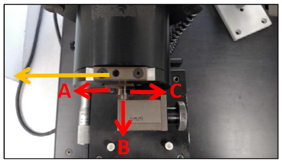
The yellow arrow indicates the bending direction, while the red arrows/letters indicate various groove orientations:
- Orientation A - groove facing pin at point of contact
- Orientation B - groove facing directly away from pin at point of contact
- Orientation C - groove facing off to the side relative to the pin at point of contact
Finally, dynamic cast resistance (DCR) testing was ran to explore the groove’s impact on the wire’s resistance to taking a permanent set when bent over a known radius under tension.
DCR Testing Results
| Sample | Arc Height | Arc Height |
| in. | mm | |
| 0.0134 Deep and Narrow | 0.49 | 12.5 |
| 0.0137 Shallow and Wide | 0.83 | 21.0 |
| 0.0134 Deep and Wide | 0.94 | 24.0 |
| 0.012 Round | 0.48 | 12.1 |
| 0.015 Round | 1.05 | 26.7 |
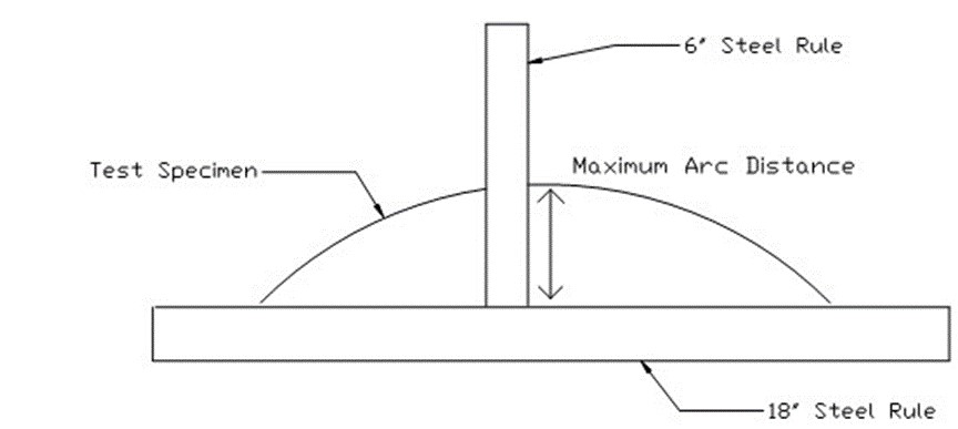
The basic DCR test method is as follows:
- Anchor one end of the wire.
- Pull the wire over a 1.38” pulley at a speed of 10”/min while a 12 ounce weight hangs from the free end of the wire.
- Remove the specimen from the test machine and remove the weight.
- With the specimen straightened, cut a 12” section from the area that has been run around the pulley.
- Measure the maximum height of the cast as shown below:
DCR Test Specimen Measurement
Ultimately, some mechanical performance is sacrificed by having the groove. However, the grooved samples all performed within a reasonable range that was bracketed out by the round wire test data. Future trials will try to optimize the mechanical properties and push strength levels towards 400 ksi. Stay tuned!
Click here to see previous highlights.
Disclaimer: Our monthly highlights are sneak peeks of what our R & D department is working on. This does not mean we have what is referenced above ready for manufacturing.